StepGen
The module StepGen is used to control stepper motors. The maximum step rate is not limited by
software or CPU, but rather by the speed of the FPGA. Based on the FPGA frequency the maximum step frequency
is tuned to be approximately 400 kHz. The maximum step frequency scales linearly with the FPGA frequency
Simlar to the LinuxCNC stepgen component,
which has both position and velocity modes, the module stepgen also has positiona and velocity
mode. The default is position control, which drives the motor to a commanded position, subject to
acceleration and velocity limits. Velocity control drives the motor at a commanded speed, subject to
accel and velocity limits. In contrast to the LinuxCNC stepgen component, one can switch between position
and velocity mode during operations.
Note
At this moment the timings can be set for each stepgen channel. At start up these timings are aggregated to a single timing which is applied to the whole stepgen. This means that the slowest drive will determine the maximum speed of the machine. In future release of LitexCNC this behavior will be changed and timings will be applied independently.
Step types
The firmware of the stepgen consist of a step generator and a pin out. The pin out is depending on
the kind of step type which is driven by the channel, which may include:
- step/dir
Two pins, one for step and one for direction.
- up/down
Two pins, one for ’step up’ and one for ’step down’.
- quadrature
Two pins, phase-A and phase-B. For forward motion, A leads B.
Step types step/dir and up/down can be driven differential. This doubles the amount of physical
pins used (i.e. step- en step+), but allows for faster driving of the drivers.
Configuration
The code-block belows gives an example for the configuration of StepGen for different step types
...
"modules": [
    ...,
    {
        "module_type": "stepgen",
        "instance": [
            {
                "pins" : {
                    "stepgen_type": "step_dir",
                    "step_pin": "j9:0",
                    "dir_pin": "j9:1"
                },
                "soft_stop": true
            },
        ...
        ]
    },
    ...
]
...
       ...
"modules": [
    ...,
    {
        "module_type": "stepgen",
        "instance": [
            {
                "pins" : {
                    "stepgen_type": "step_dir_differential",
                    "step_pos_pin": "j9:0",
                    "step_neg_pin": "j9:1",
                    "dir_pos_pin": "j9:2",
                    "dir_neg_pin": "j9:4"
                },
                "soft_stop": true
            },
        ...
        ]
    },
    ...
]
...
HAL
Note
The input and output pins are seen from the module. I.e. the GPIO In module will take an value from the machine and will put this on its respective _output_ pins. While the GPIO Out module will read the value from it input pins and put the value on the physical pins. This might feel counter intuitive at first glance.
Input pins
- <board-name>.stepgen.<index/name>.enable (HAL_BIT)
Enables output steps - when false, no steps are generated and is the hardware disabled.
- <board-name>.stepgen.<index/name>.velocity-mode (HAL_BIT)
Enables velocity mode. Default value is FALSE, in which case the positon-cmd is translated to a required velocity.
- <board-name>.stepgen.<index/name>.position-cmd (HAL_FLOAT)
Commanded position, in length units per second (see parameter position-scale). Only applicable when the pin
velocity-modeis set to FALSE.- <board-name>.stepgen.<index/name>.velocity-cmd (HAL_FLOAT)
Commanded velocity, in length units per second (see parameter position-scale). Only applicable when the pin
velocity-modeis set to FALSE.- <board-name>.stepgen.<index/name>.acceleration-cmd (HAL_FLOAT)
The acceleration used to accelarate from the current velocity to the commanded velocity. Optional parameter. When not set, the acceleration-cmd will be equal to the maximum acceleration.
Output pins
- <board-name>.stepgen.<index/name>.counts (HAL_UINT)
The current position, in counts.
- <board-name>.stepgen.<index/name>.position_fb (HAL_FLOAT)
The received position from the FPGA in units.
- <board-name>.stepgen.<index/name>.position_prediction (HAL_FLOAT)
The predicted position at the start of the next cycle. It is calculated based on the
position_fb, and the commanded speeds and acceleration. This HAL-pin should beused asfeedback for
motmodto prevent oscillations.- <board-name>.stepgen.<index/name>.speed_fb (HAL_FLOAT)
The current speed, in units per second.
- <board-name>.stepgen.<index/name>.speed_prediction (HAL_FLOAT)
The predicted speed at the start of the next cycle. It is calculated based on the
speed_fb, and the commanded speeds and acceleration.
Parameters
- <board-name>.stepgen.<index/name>.frequency (FLOAT / RO)
The current step rate, in steps per second, for channel N.
- <board-name>.stepgen.<index/name>.max-acceleration (FLOAT / RO)
The acceleration/deceleration limit, in length units per second squared.
- <board-name>.stepgen.<index/name>.max-velocity (FLOAT / RO)
The maximum allowable velocity, in length units per second.
- <board-name>.stepgen.<index/name>.position-scale (FLOAT / RO)
The scaling for position feedback, position command, and velocity command, in steps per length unit.
There are five timing parameters which control the output waveform. No step type uses all five, and only those which will be used are exported to HAL. The values of these parameters are in nano-seconds, In the timing diagrams that follow, they are identfied by the following numbers:
‘steplen’ = length of the step pulse.
‘stepspace’ = minimum space between step pulses, space is dependent on the commanded speed. The check whether the minimum step space is obeyed is done in the driver.
‘dirhold_time’ = minimum delay after a step pulse before a direction - may be longer
‘dir_setup_time’ = minimum delay after a direction change and before the next step - may be longer
Timing parameters - step/dir
The timing diagram for both step/dir is shown below. There is no Difference
in timing diagram when differential output is used.
           _____         _____               _____
STEP  ____/     \_______/     \_____________/     \______
          |     |       |     |             |     |
Time      |-(1)-|--(2)--|-(1)-|--(3)--|-(4)-|-(1)-|
                                      |__________________
DIR   ________________________________/
The relevant parameters which are exported to the HAL are:
- <board-name>.stepgen.<index/name>.steplen (FLOAT)
The length of the step pulses, in nanoseconds. Measured from rising edge to falling edge.
- <board-name>.stepgen.<index/name>.stepspace (FLOAT)
Space between step pulses, in nanoseconds. Measured from falling edge to rising edge. The actual time depends on the step rate and can be much longer.
- <board-name>.stepgen.<index/name>.dir-hold-time (FLOAT)
The minimum hold time of direction after step, in nanoseconds. Measured from falling edge of step to change of direction.
- <board-name>.stepgen.<index/name>.dir-setup-time (FLOAT)
The minimum setup time from direction to step, in nanoseconds periods. Measured from change of direction to rising edge of step.
Timing parameters - up/down
Not implemented yet.
Timing parameters - quadrature
Not implemented yet.
Example
The code below gives an example for a single axis, using the step-dir step type.
loadrt [KINS]KINEMATICS
loadrt [EMCMOT]EMCMOT servo_period_nsec=[EMCMOT]SERVO_PERIOD num_joints=[KINS]JOINTS
loadrt litexcnc connections=[LITEXCNC](CONNECTION)

# Add the functions to the thread
addf [LITEXCNC](NAME).read servo-thread
addf motion-command-handler servo-thread
addf motion-controller servo-thread
addf [LITEXCNC](NAME).write servo-thread

[...]

STEPGEN - X-AXIS
########################################################################
# - Setup of timings
setp [LITEXCNC](NAME).stepgen.00.position-scale   [JOINT_2]SCALE
setp [LITEXCNC](NAME).stepgen.00.steplen          5000
setp [LITEXCNC](NAME).stepgen.00.stepspace        5000
setp [LITEXCNC](NAME).stepgen.00.dir-hold-time    10000
setp [LITEXCNC](NAME).stepgen.00.dir-setup-time   10000
setp [LITEXCNC](NAME).stepgen.00.max-velocity     [JOINT_2]MAX_VELOCITY
setp [LITEXCNC](NAME).stepgen.00.max-acceleration [JOINT_2]STEPGEN_MAXACCEL
# setp [LITEXCNC](NAME).stepgen.00.debug 1
# - Connect velocity command
net xpos_cmd joint.0.motor-pos-cmd => [LITEXCNC](NAME).stepgen.00.position-cmd
net xpos_cmd joint.0.motor-pos-fb  <= [LITEXCNC](NAME).stepgen.00.position-prediction
# - enable the drive
net xenable joint.0.amp-enable-out => [LITEXCNC](NAME).stepgen.00.enable
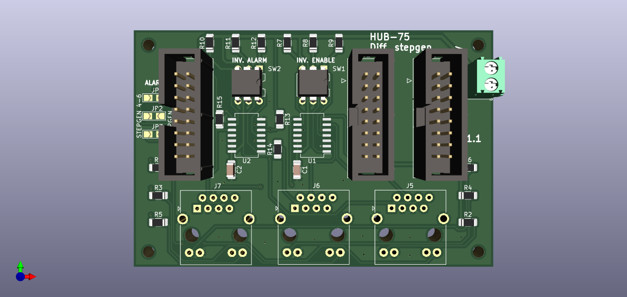
Break-out boards
For low performance (<1 kHz steprate) the default 12 channel sourcing output can be used. This might be sufficient for toolchangers are other slow moving devices.
For faster movements, you can either: - directly connect the output (5 volt) to the stepper driver; - use the stepper break-out board. This board does not provide any isolation,
but handles both the enable and alarm signals and provide output with RJ45 connectors.